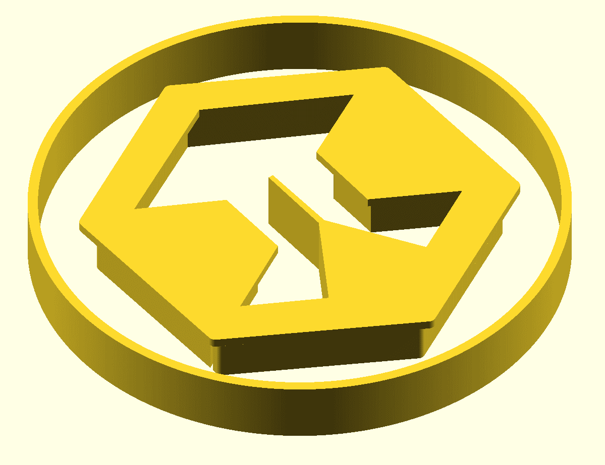
In this post, I’m excited to share my journey designing a custom 3D logo for QubiCast using OpenSCAD. This project combines parametric design, SVG-based vector art, and some creative boolean operations to produce a logo with integrated LED recesses and even a placeholder for a Raspberry Pi Pico W PCB. Here’s how I built it step by step.
Project Goals
My primary goals for this project were:
- Parametric Flexibility: Allowing easy adjustments of key parameters such as overall scale, thickness, and LED recess depth.
- Modular Structure: Breaking the design into self-contained modules (e.g., rings, hexagons, LED spaces) to simplify modifications and experimentation.
- Integration of SVG Art: Using externally created SVG files to replicate the original logo one-to-one.
- Real-World Application: Including a placeholder module for a Raspberry Pi Pico W PCB to simulate where electronics might be integrated and play around with multiple options.
Code Overview
The final OpenSCAD code is modular. It defines several modules:
SVG Import and Centering:
I created modules such as hexagon(), and inner() that import SVG files. Since the imported SVGs were not automatically centered, I applied a translation based on a manually determined center_offset to bring them to the origin.module hexagon(){ translate([-center_offset[0], -center_offset[1]]) import("hexagon.svg"); } module inner(){ translate([-center_offset[0], -center_offset[1]]) import("inner.svg"); }Generating the Ring:
The ring was generated in two ways: one using SVG imports for the artistic outline and another with a pure geometric approach using circle() primitives inside a difference() operation. This helps me create both the outer boundary and the inner cutout with a consistent ring width.outer_diameter = 170; inner_diameter = 170 * scaling; linear_extrude(height = thickness){ difference(){ circle(d = outer_diameter); circle(d = inner_diameter); } }LED Recess:
In order to be able to stick LED strips into the final design, two steps are taken—defining the cutouts and applying them via boolean logic. One module represents a scaled version of the hexagon. Another one uses a manually scaled .svg of the inner part of the logo. To generate the actual cutout, nested difference operations are used to achieve the desired LED recess—a pocket in the design where LEDs will be mounted, as well as an overhang which prevents direct view of the LEDs.module innerLedRecessForm(){ translate([-center_offset[0], -center_offset[1]]) import("expandedInner.svg"); } difference(){ scale([scaling, scaling, scaling]) hexagon(); innerLedRecessForm(); }Internal Cutouts:
Using simple polygons, I defined cutouts to both reduce weight and material, and to make place for the wiring. These cutouts are conditionally added with boolean flags, so they can easily be omitted, depending on the usecase. Again, the difference() operation function applies the polygons defined in a seperate cutouts() module for readability. Finally, the 2D information we added is extruded into a 3D object.// Inner, recessed portion of the 3D Design linear_extrude(height = thickness){ difference(){ difference(){ scale([scaling, scaling, scaling]) hexagon(); innerLedRecessForm(); } cutouts(); } } // Flat Hexagon with the Logo linear_extrude(height = thickness - ledHeight){ difference(){ hexagon(); inner(); } } // Outer Ring linear_extrude(height = thickness){ difference(){ circle(d = outer_diameter); circle(d = inner_diameter); } }Raspberry Pi Pico W Placeholder:
Lastly, there’s a module called picoW() that creates a simple cuboid as a stand-in for a Pico W PCB. This allows me to visualize how the board might integrate with the logo design.module picoW() { // Create a cube with the Pico W dimensions, centered at (0,0,0) cube([51, 21, 5], center = true); }

Final Thoughts
This project was a great exercise in combining vector art with procedural 3D design. By leveraging OpenSCAD’s modularity and boolean operations, I was able to "code" a detailed and customizable 3D logo for QubiCast. Whether you’re working on branding, enclosures, or even PCB integrations, a parametric approach can save you significant time and open up a world of possibilities.
I hope you enjoyed this dive into my design process. Feel free to check out the code, tweak the parameters, and share your own experiments!
Happy coding and 3D printing!
Philipp