DMX512 is probably the most widely used lighting control protocol in the world. It's also one of the most widely misused. The ANSI E1.11 standard that defines it is specific about how DMX systems should be built: Connectors, cabling, termination, device limits. In practice, half the industry ignores at least one of these rules on every show.
Here are five things the standard actually says, and how commonly they're broken.
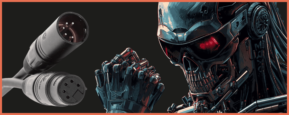
1. 3-Pin XLR Connectors Are Prohibited
Section 7.1.2 of ANSI E1.11 doesn't just recommend 5-pin XLR, it explicitly prohibits any other type of XLR connector for DMX. If a 5-pin connector physically won't fit on a device, an alternate non-XLR connector is allowed, but using a 3-pin XLR is specifically ruled out.
The reason is practical: 3-pin XLR is the standard connector for audio equipment. If your DMX cables use the same connector, there's nothing stopping someone from plugging a DMX cable into a mixing console output carrying 48V phantom power. That voltage goes straight into a DMX input circuit that isn't designed for it.
In reality, 3-pin DMX is everywhere. Budget fixtures ship with it, rental houses stock drawers full of 3-pin DMX cables, and most working technicians have used them without a second thought. It works… until someone connects the wrong cable to the wrong device.
2. Every DMX Line Must Be Terminated
ANSI E1.11 requires a 120Ω resistor between Data+ and Data- at the far end of every DMX line. This isn't optional, it's in the spec because unterminated lines cause signal reflections that corrupt data.
DMX best‑practice guides state that incorrect or missing termination is ‘probably the single most common reason for faulty DMX512 systems.’
ETC's own documentation notes that DMX may appear to work without termination, but that a small change to the network (adding a cable, connecting another fixture) can suddenly introduce flickering, twitching moving heads, or intermittent control loss.
In the real world, most short DMX runs work fine unterminated. This creates a false sense of security. Technicians learn that terminators are "not really necessary" because they've never had a problem until they add three more fixtures and the entire rig starts flickering five minutes before doors.
3. Maximum 32 Devices Per Line
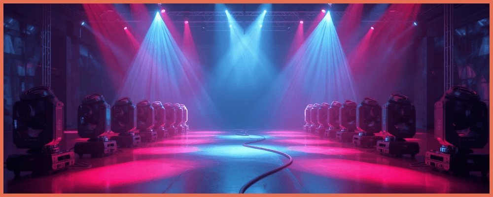
The EIA-485 electrical standard underlying DMX limits a single bus to 32 unit loads. Each DMX receiver adds electrical load to the signal, and beyond 32 devices, signal degradation becomes a real risk. The solution is a DMX splitter or repeater, which regenerates the signal and creates a new segment that can support another 32 devices.
ENTTEC recommends an even more conservative limit of 16 fixtures per cable run. In practice, plenty of rigs exceed 32 devices on a single line, especially in architectural installations with large numbers of small LED fixtures daisy-chained together. It often works at first but becomes unreliable over time as connectors age and cable impedance drifts.
4. Microphone Cables Must Not Be Used for DMX
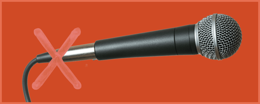
DMX requires cable with a characteristic impedance of 120Ω. A standard microphone cable typically runs 45–75Ω which is roughly half the required impedance.
ETC's documentation is direct about this: "microphone cable or other non-rated cable must not be used to carry DMX." The impedance mismatch causes signal reflections that worsen with cable length and the number of connected devices. Short runs may work fine, but the failure mode is unpredictable. DMX tends to work perfectly right up until the moment it stops working entirely, with no gradual degradation warning.
The ControlBooth forums have years of debate on this topic.
One experienced technician summarized it well:
mic cable for DMX is like getting away with it until you can't, and when it fails, it fails during the show.
The impedance mismatch doesn't cause a gentle decline, it causes sudden, intermittent failures that are extremely difficult to diagnose.
5. No Y-Splits Ever

DMX is a bus topology. The standard requires a single daisy chain from controller to devices. Y-splitting a DMX line (using a two-fer or passive splitter to feed two branches from one output) creates an unterminated stub that acts as an impedance discontinuity. The reflected signals from the stub can corrupt data on the entire line.
The correct approach is always an active splitter (also called an opto-splitter or repeater), which electrically isolates each output and regenerates the signal. Passive Y-splits may appear to work on short runs with few devices, but like every other item on this list, they work until they don't and they tend to fail in ways that are maddening to diagnose.
The Pattern
Every one of these rules gets broken for the same reason: it works anyway, most of the time. Short runs, simple rigs, and favorable conditions mask the consequences. The problems show up when the rig grows, the cables get longer, the connectors get worn, or the environment introduces electrical noise. By then, the symptoms (flickering fixtures, intermittent control loss, random behavior) look like equipment failure, not a standards violation that's been quietly waiting to cause trouble.
The DMX512 standard is defined this way because people with a lot of patience figured out what breaks under load. Following it isn't about being a purist. It's about not creating a mystery failure at 6 PM on a Friday.